Traction engine.
I
was about eleven or twelve when I first attempted to build a steam
engine. The first attempt was a very rough piece of engineering, I
was young so can be excused. The boiler was galvanised steel, soft
soldered together, which amazingly produced steam. The engine was a
co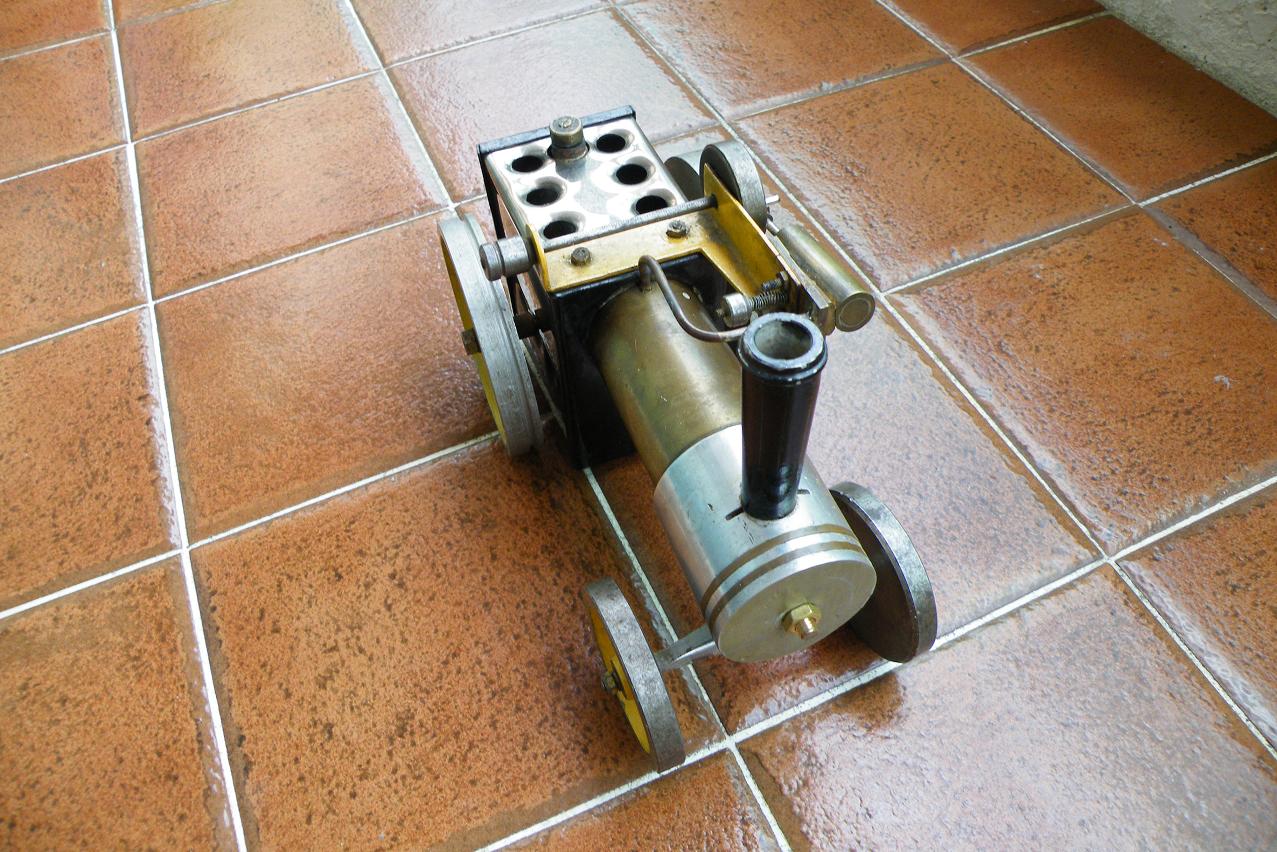 llection of chainsaw parts and other pits scrap. My equipment
consisted of hand file, hacksaw, electric hand drill and a soldering
iron. The design of the engine came of a diagram in an encyclopaedia.
The engine did not run, but think back, I believe the problem was
with the valve timing. I did not know enough about the valve timing
at the time, I had the erratic in line with the crankshaft, when it
should have been at 90 degrees, but you live and learn.
llection of chainsaw parts and other pits scrap. My equipment
consisted of hand file, hacksaw, electric hand drill and a soldering
iron. The design of the engine came of a diagram in an encyclopaedia.
The engine did not run, but think back, I believe the problem was
with the valve timing. I did not know enough about the valve timing
at the time, I had the erratic in line with the crankshaft, when it
should have been at 90 degrees, but you live and learn.
Then
one day, a metalwork teacher was in the workshop and seen the engine,
so he gave me a book on now to build a simple wobble steam engine.
The book had two engines, a stationary engine and a traction engine.
Me being me, went for the more adventurous build the traction engine.
I got a piece of copper tube from a plumbing friend of ours, so that started the build. Had some trouble with the brazing of the boiler, so had a friend try to braze it for me, he told me that copper can be difficult to braze at times, so it it does not braze, let it cool down and try again. It would be better to use silversolder, but we only had brass. So he was able to braze it for me.
The boiler would be heated by methylated spirits, so the burner was a simple tray, lined with glass fibre, with a grill on the top. I made the tray out of brass, don't know where I got it from, probably my plumber friend again. Soldered the whole unit together and it worked fine.
The
firebox around the boiler was stainless steel and mild steel sheet.
The stainless steel came for an old washing machine, again courtesy
of my plumber friend. I made a tool, that was given in the book, to
form the flanged holes.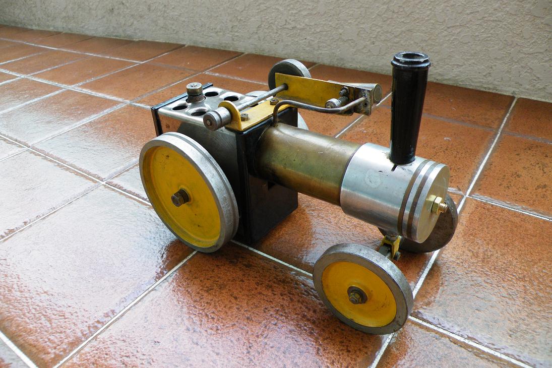
The front of the engine and the funnel was a casting, needless to say I could not cast it. So had to come up with an alternative. So looked around the workshop and found an old chainsaw piston that worked for the front. But what to make the funnel with. Don't know what gave me the idea, but decided to cast an aluminium bar and machine it to make the funnel. So I broke up an old lawnmower aluminium engine block. Melted the aluminium pieces, using a gas torch in an pan make of the back of an old rear axle cover. The mould for the bar was a steel pipe, pored the melted aluminium into the steel pipe. But it did not work, just got lumps. Did some brain storming, the aluminium solidified into lumps when it touched the cold steel pipe. So another attempt was made, this time preheated the pipe before pouring the aluminium. The result was not perfect, but there was enough of a solid bar to make the funnel. In the meantime, we got a small lather in the workshop, so was able to machine it myself. The bottom of the funnel was a interference fit for the gudon pin hole of the piston, so pressed them both together. Another small block was used in the other gudion pin hole for the axle boss.
The wheel was also cast aluminium, so decided to make them out of steel. So went to a local metalwork shop where they had acythaline torch profile cutter, but it could not cut the wheel spokes good enough. So decided on solid wheels, so machined them out of steel bar.
The engine frame was a made out of sheet steel drilled and folded to create the bearing and engine support. The drive shaft is a welding rod with a machined pulley on the end. The fly wheel is a steel bar machined with a recess on one side and a off set hole of the conrod. The cylinder is a brass tube reamed out, with a filed flat on one side for the flat plate, which was soldered on. Another brass plate is bolted to the engine frame of the cylinder to slide on. The pistion was make from brass, with a steel conrod and a brass conrod end. The copper piping was got from old chainsaws.
All
was assembled and the engine was running freely. Now it was time to a
fill the boiler and light the methylated spirits. Soon there was a
sound of steam hissing. A flick of the flywheel and the engine ran.
Stopped the engine and added a rubber band over the wheel and drive
pulley. Flicked the flywheel again, but it would not drive, removed
the rubber band and the engine ran fine. So concluded that the rear
steel wheels were too heavy, needed aluminium wheels. But where to
get the aluminium bar? My father suggested tractor pistons, so off to
a guy who repaired tractors, he had piston the right size, so on the
lathe and machined the rear wheels. With the new wheels on the
traction engine, we made another attempt at driving. This time we had
success, the traction engine drove around the kitchen floor, had to
keep chasing it to steer it away from crashing, but it was fun and I
was delighted that I had got my first engine running.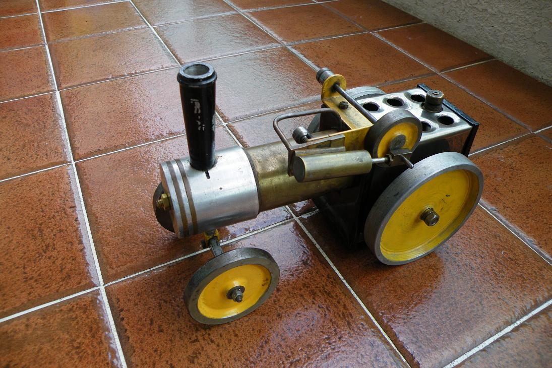
I ran it a few times, at school and at friends houses. Years later, when I was home on holidays from Hong Kong, I looked for the traction engine. I found it, but it was in two pieces. The front had been bolted to the boiler by a metal bold brazed to the boiler. This had rusted away. The original design called for a brass bar all the way through the boiler. So I brought the traction engine back with me to Hong Kong. There I got a brass rod, bored the ends of the boiler and brazed the brass rod into the boiler, this time with silver solder. Reassembled the traction engine and got it ready to run again. I did not have any methylated spirits, but got one of those can with flammable gel that goes under food warmers. Open the can, took out the gel, put it in the burner and lit it. Soon the water was boiling, so spun the fly wheel, it spluttered, ran a few turns and stopped, condensation in the cylinder. Let the boiler heat up more and another spin of the flywheel and off it ran. I ran just the same way it ran years ago.
Just a not for anyone that wants to build a traction like this, the flames from the methylated spirits can come out through the holes in the top of the firebox. If I was going to build a new one like this, I would see if I could stop this from happening or use a different fuel.
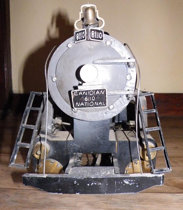
The locomotive
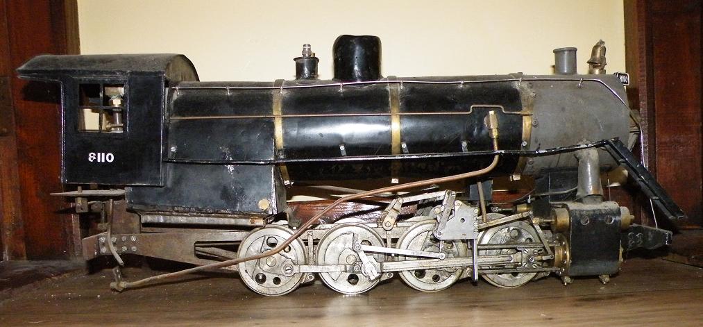
The locomotive took four years to build, so I will not go into detail, just a few points that I can still remember.
When I got the plans for the locomotive, I was sitting exams at school. So while the other students were cramming for the exam, I was looking at my locomotive plans.
The boiler was steel tube and flat steel plate to make the fire box. There is four large flue pipes for the stem super heaters, so used hydraulic pipes here. There was no leaks when I pressures tested the boiler, so I was happy.
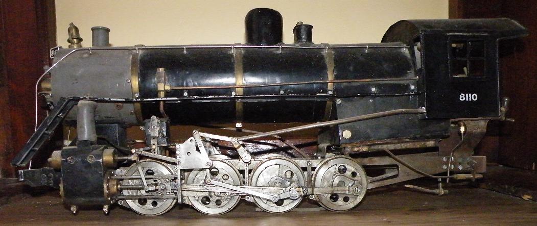
The chassis frame called of 9mm plate, I had only 6mm plate, so machined the chassis out of the 6mm and added 3mm plates to the areas for the wheel bearings to make up the width.
The wheel bearing were made from steel, but altered the design, I used chainsaw roller bearing to run on the axles.
For the wheels, I did not have the castings, so would machine them from solid steel, but did not have big enough steel bar. So got a pin from a digger, right size, but a problem,it was case hardened, so it was hard to machine, but them they would not wear.
The cylinders were casting, which I did not have, so needed an alternative. Laying around was an larger diameter flywheel, it had a counter weight bolted onto it and it was cast iron. So cut two chunks out of it for the cylinders. I needed a four jaw chuck to machine the bores, but the local machine shop did not have a four jaw chuck. But we had a friend who was a maintenance engineer in a sweet factory, which had a four jaw chuck. So one weekend when there to machine the bores. The factory had a larger supply of materials, one which was brass bar, the right size to make liner for the cylinders, so machined out the piston bores oversize and machine the brass bars into liners and fitted to the cylinder blocks. He gave me some brass bar to make the valves and valve liners, which I could machine at home.
The locomotive was designed to be fired by coal, but I wanted to use gas. So I came across drawing for a gas burner. So I built it and modified it to suit my boiler. The design required a small hole is to be drilled in the gas nozzle, but I did not have a drill the right size, so drilled using the closest drill I had. On the first fire up, the burners used all the gas in the cylinder in a few minutes. So went for a bigger gas cylinder. But still used a larger amount of gas and the boiler was slow to build up pressure. So I decided to look at the gas nozzles again. I checked the hole size and the hole size was too big. Still did not have the right size drill bit, so instead of trying to make new gas nozzles, I squeezed the gas nozzle to make the holes smaller. The next fire up, the gas usage was a lot less and the boiler heated up a lot quicker. So gas burner working, even though had to tweak it in an unconventional way.
The
locomotive used Park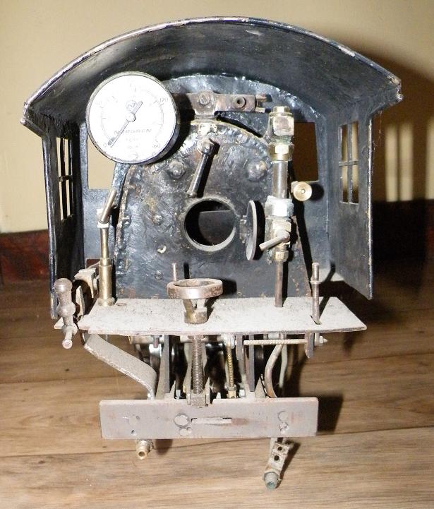 er valve gear. One linkage was curved, but I
straightened the curve to a straight link. I make all the links and
assembled then as
er valve gear. One linkage was curved, but I
straightened the curve to a straight link. I make all the links and
assembled then as
I seen in the plans. So went to run the engine
on air. The engine ran forward, but when tried reverse, the engine
would not run. Looked at the linkages again, reset the cranks and
tried again. This time ran in reverse, but not forward. So was
confused. Went back to the linkages and looked at them again. Then I
realized that the linkage that was designed curved and I straightened
out was reversed. There was only an assembly drawing showing the
linkages and parts of the linkages were hidden by a plate, so I did
not know that the linkage was in wrong. So reversed the linkage,
connected to the compressed air and success, engine now running
forward and reverse.
So
the locomotive was ready to run under steam. I had made a blower form
an old vacuum cleaner fan and a 12volt motor. So filled the boiler
and lit the gas. Soon the boiler was heating up and building steam.
But there was a problem, there was steam entering the cylinders, the
regulator was leaking. So shit down and let it all cool down. Opened
the steam dome, the regulator design has a flat slide on the top to
regulate the steam, it had warped with the heat. Made the slide flat
again and reassembled. Steamed up again, but it still leaked. Opened
the steam dome again and the slide was warped again, it was the wrong
material. But I did not have the navel brass as required in the
design. So a redesign was required. So I came up with a ball bearing
sitting on top of a seat, the regulator was opened by a cam that
knocked the ball off the seat. So steamed up again, this time no
leak. The pressure built up to 90psi and I opened the regulator and
away the locomotive went along my short length of track under its own
steam, with me behind it on a carriage. Stopped at the end of the
track, put I into reverse and back along the track.
I ran the locomotive a few more time, but the regulator was not perfect, some times it would no open and did not regulate the steam. I always intended to rebuild the components that gave problems, the regulator and the wheel bearings. Started to do this when I was working in Cork, but started another project which took all my time, I built a house. I intended to build a workshop beside the house, but moving to the UAE stalled that. The locomotive is in my parents house gathering dust, but I will get it over here some time and hopefully get it running again.
Other crazy builds
Go-karts.
One of my memories is of a go-kart that myself and my brother built. It was any ordinary go-kart, a few pieces of wood, two rear wheel and two front wheels steered by a pull rope. But that where the normality stops, we added an engine, took the tyre off one of the rear wheel, ran a belt around the rim and a pulley on the engine. Started the engine and off it went, but without anyone on the go-kart, none of us was brave enough to get on.
This was the beginning, several go-kart were build using various chassis design and power trains. Most used a belt drive and circumifical clutch, rev the engine and off you go. The our father go an scrap industrial lawnmower, so we could build a go-kart from it. We used the wheels and gearbox, built a steel chassis from angle iron and a strong steering. It had a three speed gearbox, with a reverse and a five horsepower engine. When it was ready for a test drive, my brother took the test drive, when he took off, I remember my father saying “I did not think it would be that fast” We drove it for years, mostly at the weekends. We mainly drove in the fields, so ever so often had to perform repairs.
Microlight.
Yea I tried to build one, but it never flew. I build a frame and a triangle shaped wing. It had a chainsaw engine with a homemade wooden propeller. Several attempts was made to start the engine, but it never ran, luckily, probably would have seriously injured me and anyone else near by.
Helicopters.
Yes, I made two attempts at build a helicopter, I think I was around ten at the first attempt and 12 at the second attempt. Like the microlight, they never flew. Basically built the frames, the first one did not have rotors, but the second one did and I had designed a crylix system to tilt the rotors. Got the rotors to spin slowly using an electric motor, but that was far as it got.
Car.
When I was in collage, I was learning CAD, so I designed a car. I was going to use box iron to build the frame. The design had a rear mounted engine, was going to get a damaged front wheel drive car, measure the suspension points and build the frame using these points and use the suspension from the car. The engine and gearbox would be mounted in the rear and the gear shift linkages brought forward. This only got as far as the design stage.
Robots.
When I moved to the middle East the first time, I had plenty of spare time, so decided to learn something. So came up with using remote control servo motors to make them move. I searched the internet and found several designs. Use these as a basic for my own designs. I designed a few different robots, they were either two or six legged. I then looked into controlling the servos, so searched the net again. Came across a website that showed how to use a PIC chip to control up to six servos. So got the components and built the circuit with the PIC programmed using the code off the website. Got it to control the servos from the computer through the com port. I had a Pam PDA,sto messed around with that and got it to control the servos. But again, this is as far as I got. I still have the designs and might look again at them sometime.