25
September 2010.The
flat bar for the steam engine base was not thic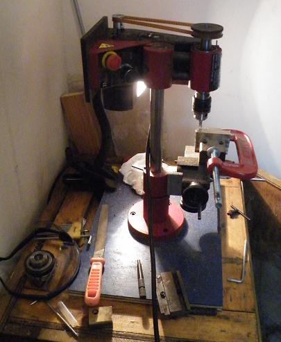 k enough, so brazed 4
flat sections to increase the thickness.
k enough, so brazed 4
flat sections to increase the thickness.
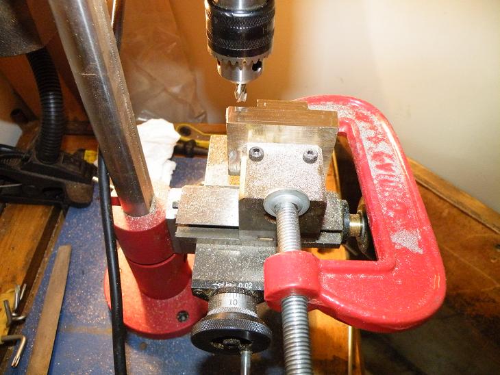
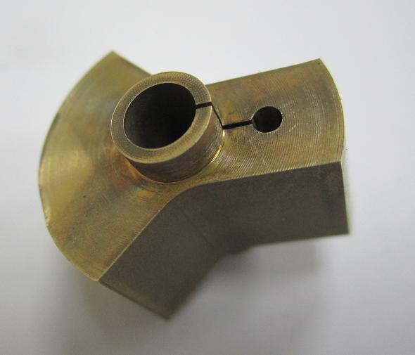
Converted the lathe into the milling machine. But the travel of the slides is restricted and the Z height is also restricted. See now why its best to have a proper mill. So had again to do a work around. Used a brass block bolted to the top slide. Could not use the mill table, as it reduced the Z height to much. So used the brass block as an angle plate and a G clamp to hole the base. Milling the base block length ways, using the Y axis. Still there was just travel to machine.
The bearings in the motor was starting to noise and the motor was loosing power. So I decided the look at the bearings and see if I could fix them before the motor damaged itself. I opened the motor and the bronze bearing was worn on the side that the drive belt was pulling on. So rotated the bearing 180 degrees. The shaft was pitted at the bearing position, so polished the shaft. Put the motor back and tested it. But it did not work, so checked the wires and connections, but still did not work. Opened the motor again and checked the windings. Noticed that the armature wired were damaged. The must have got damaged when I was polishing the shaft. The armature cannot be fixed so need to buy a new motor.
17 October 2011. It been a long time since I wrote any updates, Actually its been a year. Why so long? Well I have left Hong Kong and moved back to the middle east, to Abu Dhabi. So I will try to fill in what has been happing.
The motor. Did some checking and the motor was a sewing machine motor, but it was not a standard sewing machine motor. Checked around Hong Kong and could only find a standard motor, so I decided since it was cheap, to gee one and try it out. I wired the motor first and checked if it would work, it spun, but in the wrong direction. Since it was an AC motor, reversing the wires did not make a difference, so I mounted the motor mirrored to the original mounting position, so the motor drove the lathe in the correct direction.
Soon after replacing the motor, I moved to Abu Dhabi, so it was a few moths before I was able to setup to start work on the engine again.
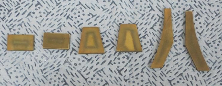
At the new job, there was a copper pipe removed and thrown outside, so I checked with my manager and I could have the pipe. The pipe was the correct size for the water tank and gas tank. I cut two lengths for the water tank and gas tank. I cut more to make the end caps. I cut 4 blanks and was wondering how would I form them. I decided that I would make a form tool. The base for the mill was nearly the right diameter, just needed to turn the diameter down a millimetre, so did that on the lathe at work. Then I needed a outer ring to form the press. So I looked around again at work and found a pipe fitting. It was the correct side, just needed the weld seam smoothed and the end squared. So filed the weld seam and squared it on the lathe at work. Then I annealed the 4 end caps and then used the hydraulic press at work to press out the end caps. It worked well and the ends caps fitted the tank tubes perfectly.
I setup the lathe in the electrical room of the house, as there was space to have a small workshop. I converted the late to the mill and machined the two blocks for the bearing holders.
The heat is too much to try and do some work in the room, as the temp was reaching 45DegC,so was not able to do any work, even with a fan.
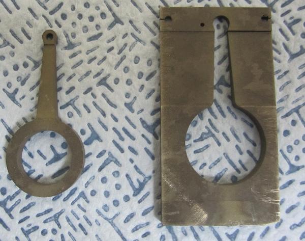
I was able to use some of the equipment at work to make some parts. The first was to machine out the center of the base. There is a wire EDM machine at work, so learned how to program it and cut the center out.
Next
I cut the parts for the column, again on the wire EDM. The wire EDM
allowed me to cut the slot it the foot plate for the vertical plates.
The center of the column was a brass bar, that I would drill and
ream later for the piston guide. The column needs to be assembled
correctly, so by having slots in the center column will ensure that
the column will correctly assembled. So wire EDM again. The top of
the column had a slot machined in it, the column had a rise machined
into it and slots in the side. This would ensure correct alignment
for assembly. But, there was an error during machining, the rise on
the column was out of position, so I would need to machine it again,
but I was short of brass, so decided to file the raise so the error
could be corrected. So I did this and it worked out fine.
There was some scrap parts at work made from Inconel 738 alloy, so I decided to cut the erratic rod from this. I wired EDM the side profile of the rod, then EDM two pilot holes for the erratic hole and the pin hole. Then wire EDM the holes to the correct diameters, then cut the shape of the erratic rod.
The I turned my attention to the con rod. Same procedure as for the erratic rod. I did not leave any extra material on the top of the conrod, I was slightly out in the positioning for cutting the plan profile, so the wall at the conrod pin is thin. Was going to re-cut again, but decided not to and use the conrod as is, I will build the engine with it and if its not strong enough, I will make another one later.
I was going to use the CNC mill to pilot drill the holes on the base, but it was busy, so used a die sink EDM machine with a DRO to drill a start hole, then I later drill out using a pillar drill. Before I taped the holes for the bearing housings, I clamped the bearing housing and drilled through the bottom of the base to make the hole position, this ensure that the bolt holes would be aligned. Then I drilled the holes in the bearing blocks.
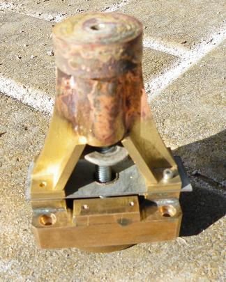
22 Dec 2011. Decided to attempt the brazing of the column. It would be a two stage process, the top disc, column and curved plate plates first, then the feet and side plates next. I had already got two flat plates and bolted them together as a clamp for the flat curved plated. They held the plates good enough. Next was to clamp the top disc to the column bar, was thinking how I would do this, first I was going to drill a hole through the top disc, tap the column and bolt together. But decided against this, as I wanted to use a 4mm tap, but had none. So drilled a 4mm hole though the top and column, then used a long 4mm bolt. So bolted the top and column together, then slid the flat plates into their slots. All held together good enough for brazing, so setup for brazing. So setup the assembly on a metal column for brazing and lit the gas. It took a while for the assembly to get hot enough for the silver solder, but once it was hot enough, the braze ran easily. So first half done.
 23
Dec 2011. Now the next stage of the brazing of the column assembly.
Cut a plate of galvanized steel as a spacer between the base and the
feet. This would prevent any braze run from brazing the feet to the
base. Then bolted the feet to the base, using one bolt per foot, as
only had a few 2mm bolts. Then needed to hold the first brazed
section onto the feet. So went back the tapping the column again.
Searched for a long enough bolt, then remembered I had bolt from a
IKEA unit, found it and it was lone enough. So tapped the column and
bolted the first assembly to the base. It worked great. Next was to
fir the two side plates. They needed a bit of filing to get them to
fit, so out with the file and after a few minutes had them fitting.
But now, how to clamp then into position. Was thinking of a round bar
with a hole through it, then use the bolt holding the assembly
together with a nut to hold them. But did not have a suitable bar to
hand. So looked around and found a washer. This worked, so after a
bit of fiddling with the bolt and nut, had all the part assembled and
ready for brazing.
23
Dec 2011. Now the next stage of the brazing of the column assembly.
Cut a plate of galvanized steel as a spacer between the base and the
feet. This would prevent any braze run from brazing the feet to the
base. Then bolted the feet to the base, using one bolt per foot, as
only had a few 2mm bolts. Then needed to hold the first brazed
section onto the feet. So went back the tapping the column again.
Searched for a long enough bolt, then remembered I had bolt from a
IKEA unit, found it and it was lone enough. So tapped the column and
bolted the first assembly to the base. It worked great. Next was to
fir the two side plates. They needed a bit of filing to get them to
fit, so out with the file and after a few minutes had them fitting.
But now, how to clamp then into position. Was thinking of a round bar
with a hole through it, then use the bolt holding the assembly
together with a nut to hold them. But did not have a suitable bar to
hand. So looked around and found a washer. This worked, so after a
bit of fiddling with the bolt and nut, had all the part assembled and
ready for brazing.
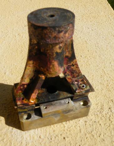 Setup
the assembly on the metal column again. Lit the gas and heated the
assembly up. The brazing of the first corner did not go well, the
assembly was just not hot enough, but stuck with it. Then tried the
second corner, it did not go as well as the first corner, left a few
big lumps of silver solder. So went onto the third corner, this time
I was lucky, the silver solder run easily, had it brazed in a few
seconds. Then onto the forth corner, nearly as good as the third
corner, had one lump of silver solder, so held the gas torch on the
assembly and tried to make the lump run. It worked, the lump ran and
the joint was smooth. So turned my attention back to the first two
corners and after a few minutes of heating, got the limps to run. It
was not perfect, but with a bit of dressing, the imperfections can be
dressed out. I am going to grit blast the surfaces, to give a casting
effect, so the surfaces do not have to be perfectly smooth.
Setup
the assembly on the metal column again. Lit the gas and heated the
assembly up. The brazing of the first corner did not go well, the
assembly was just not hot enough, but stuck with it. Then tried the
second corner, it did not go as well as the first corner, left a few
big lumps of silver solder. So went onto the third corner, this time
I was lucky, the silver solder run easily, had it brazed in a few
seconds. Then onto the forth corner, nearly as good as the third
corner, had one lump of silver solder, so held the gas torch on the
assembly and tried to make the lump run. It worked, the lump ran and
the joint was smooth. So turned my attention back to the first two
corners and after a few minutes of heating, got the limps to run. It
was not perfect, but with a bit of dressing, the imperfections can be
dressed out. I am going to grit blast the surfaces, to give a casting
effect, so the surfaces do not have to be perfectly smooth.
Got some shelves from IKEA, the room was getting a untidy. So pulled out all the stuff from the back of the room, then setup the shelves and put the stuff back, now easier to find stuff. So with my tidy up done, turned my attention back to the brazed column assembly. First was to undo the bolts. Was worried as one bolt was brazed with silver solder overrun. So tried the other bolt first, it came out easily. Now the brazed bolt, so tried to turn the column assembly and undo the bolt this way. It did not want to budge at first, so used the expanding pliers and it moved. The bolt unscrewed, so the worry of it being full brazed was gone. But how to remove the bolt. So gave the bolt a tap of a brass block and it shot out of the hole. Then it was the turn of the plate, it held a small bit, then gave away. So the assembly was free and looked good.
Gave the assembly a wash to remove the sticky leftover of the braze flux. Then setup a wire brush in the lathe and gave the assembly a clean. Now I could see the good and bad brazing. Thanks to the tidy up, as easily able to find some small grinding stones, so into the lathe with one of them and started to grind off the lumps of braze. Soon the lumps were gone and just some areas to be finished later, after the first light grit blast. The grit blast will show up the braze that needs to be removed.
3 Jan 2012. Grit blasted the column assembly, now can see the braze that ran. Got some used burs at work that can use to remove the excess braze.
 4
Jan 2012. Setup
the column assembly to drill the center. There was a 10mm reamer at
work, so would use it. Need to figure out how I would hold the column
for machining. Was going to use a round disc and bolt the engine base
to it, then bolt on the column assembly to the engine base. But the
disc I was going to use, it was threaded in the center, but the bolt
head was too big to fit between the
4
Jan 2012. Setup
the column assembly to drill the center. There was a 10mm reamer at
work, so would use it. Need to figure out how I would hold the column
for machining. Was going to use a round disc and bolt the engine base
to it, then bolt on the column assembly to the engine base. But the
disc I was going to use, it was threaded in the center, but the bolt
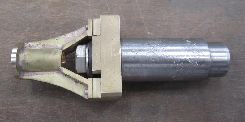
head was too big to fit between the  column assembly. So had to find
something else. Found a shaft with one end the same diameter as the
engine base center and it was threaded, so I could bolt the base to
it. The bolt head was small enough to fit between the column
assembly, so all ready to machine the column. Setup the shaft in the
lathe. First I machined the column top to the correct height. Since I
had already drilled the column, it was off center, so used a milling
cutter to pilot drill an centered hole. Then drilled using a few
drills to get to the size for reaming, then reamed the 10mm hole.
column assembly. So had to find
something else. Found a shaft with one end the same diameter as the
engine base center and it was threaded, so I could bolt the base to
it. The bolt head was small enough to fit between the column
assembly, so all ready to machine the column. Setup the shaft in the
lathe. First I machined the column top to the correct height. Since I
had already drilled the column, it was off center, so used a milling
cutter to pilot drill an centered hole. Then drilled using a few
drills to get to the size for reaming, then reamed the 10mm hole.
I then looked at the crankshaft. Turned a short length of brass, machined the bosses at each end and drilled a hole straight through.
 5
Jan 2012. Setup
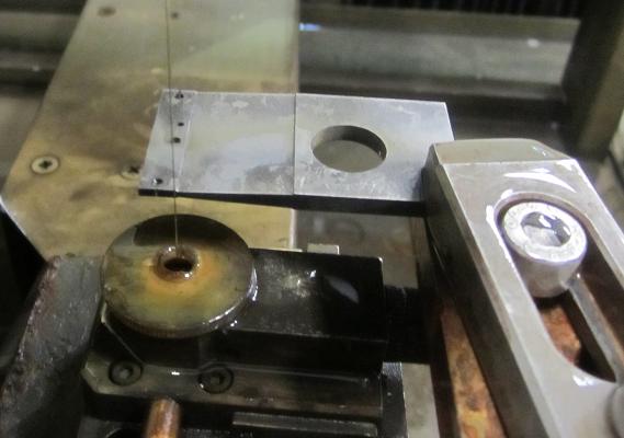
the brass for the crankshaft in the wire EDM. First drilled the
center hole to 5mm dia, then a straight line to the crank hole and
drilled a 2mm hole. The reason I did this, was to ensure that
the crank was the correct dimension from the crank, also the profile
of the crank will be correct to the crankshaft. Then cut the profile
of the crank. I removed the crank and inserted a bar into one end of
crankshaft hole, then I cut the crank into two, to make the two sides
of the crank. Back to the lathe and with the bar still in one crank
side, turned it to the correct thickness, next did the other crank.
5
Jan 2012. Setup
the brass for the crankshaft in the wire EDM. First drilled the
center hole to 5mm dia, then a straight line to the crank hole and
drilled a 2mm hole. The reason I did this, was to ensure that
the crank was the correct dimension from the crank, also the profile
of the crank will be correct to the crankshaft. Then cut the profile
of the crank. I removed the crank and inserted a bar into one end of
crankshaft hole, then I cut the crank into two, to make the two sides
of the crank. Back to the lathe and with the bar still in one crank
side, turned it to the correct thickness, next did the other crank.
Next setup the column on the mill and milled the slot in the side of the column.
 Then
setup to drill the bearing holes in the engine base. Assembled the
blocks onto the base and mounted the base in the drill press. Marked
the hole position on the split of the blocks and pilot drilled a
hole. Then drilled up in stages to the size for the reamer, then
reamered the hole to 10mm, the size of the bearings.
Then
setup to drill the bearing holes in the engine base. Assembled the
blocks onto the base and mounted the base in the drill press. Marked
the hole position on the split of the blocks and pilot drilled a
hole. Then drilled up in stages to the size for the reamer, then
reamered the hole to 10mm, the size of the bearings.
7 Jan 2012. Checked the size of the crankshaft hole against the shaft I was going to use, but It was not the interference fit I had hoped for, it was slightly loose. Checked the size of the shaft, it was 4.9mm, instead of the 5mm I though it was. I should have checked the size of the shaft before drilling the crank. So what to do? The original intention was to have an interference fit, so my only option was to silversolder the cranks to the shaft, not my ideal option. But needed to check if the shaft could be brazed, as it was a shaft from a model helicopter and it might be coated. So did a quick braze trial on the shaft and the silversolder stuck. So silver soldered the crank ends to the shaft.
Put one of the burrs in the lathe and went to work on the column and removed more of the braze over run. Got a lot of it removed and the corners no longer have lumps of braze. Need to blast it again, to see where the braze still remains, I want to remove the excess braze so it will just look all brass.
8 Jan 2012. Drilled the 4mm holes in the crank today. Made a crank pin from brass and taped it. Press fitted the pin into the crankshaft. Assembled the crankshaft and assembled it into the engine base. Gave it a spin, but the shaft wobbled. Reckon, the shaft is not at true right angle to the cranks, so will give it a spin in the lathe to see if its off. I reckon I should have brazed the shaft into the cranks before I split them into two, then the shaft would be square, need to remember for next project.
28 Jan 2012. Did a small bit today. Dress some of the silver solder off the column. Trying to remove as much as possible so only see brass when finished. I am not going to paint the column, I want the brass to be seen.
31 March 2012. Been a while since I did some work. So decided to braze the water and gas tanks. So as with the boiler, wanted to heat the tanks prior to brazing. So I purchased a camping stove. Prepared the tanks, clea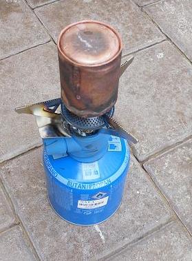 ned the areas to be brazed and applied braze flux to one end of the tanks. Then lit the stove and placed the first tank on top. When the tank was hot, the flux boiled away and I started with the torch. Soon the copper was cherry colour and brazed easily. Did the same for the second tank. Then when cool, cleaned the other end of the tanks, fitted the ends and applied the braze flux. Th
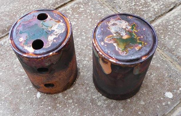 en as before, heated them with the camping stove and brazed with the torch, again they brazed easy. I need to clean then tanks, so looking to make a pickle bath to clean them. Might see I can do this at work or try at home. Found an article saying that distilled vinegar. Might get some and do a trial.